A couple of months ago I saw an old grandfather clock that someone had fit a piece of acrylic to. All of the brass gears and the escapement on the inside were revealed in fascinating detail. Ever since, I’ve been thinking about building a clock with exposed gears.
Design and CAD
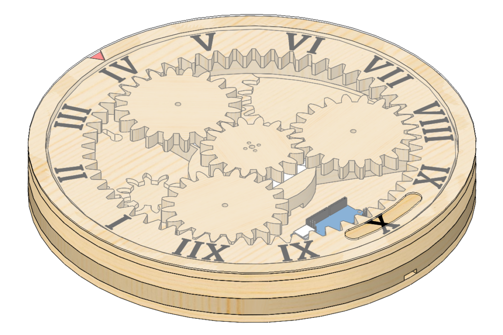
I wanted to start simple: Just something that would keep track of the hours. Think, “mechanical sundial.” I started by picking out the slimmest NEMA 17 stepper motor I could find and I went to work in Solidworks…
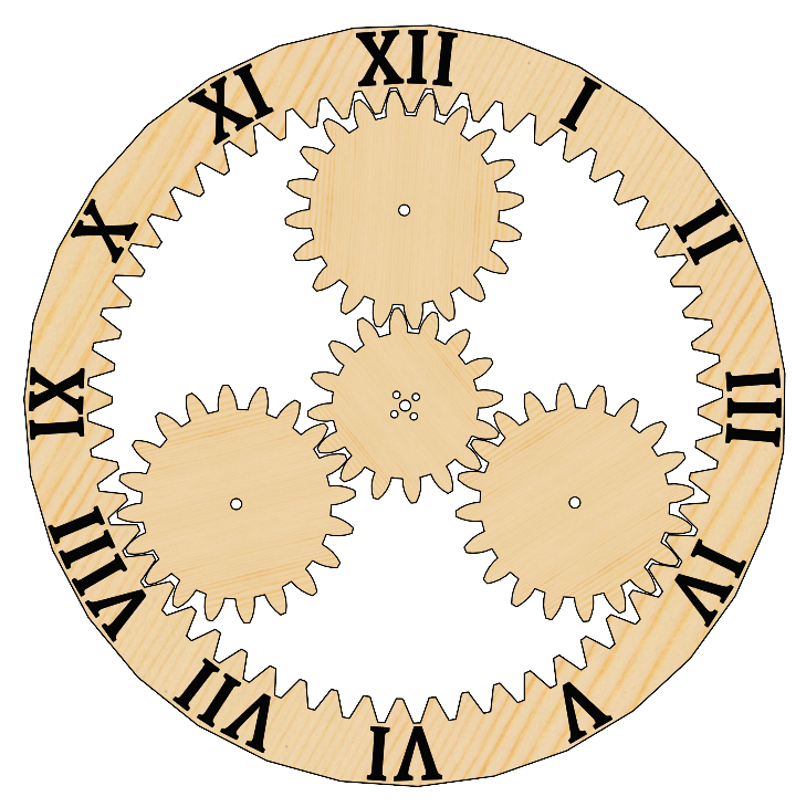
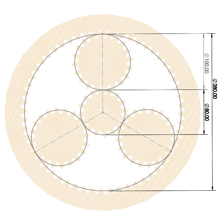
The design is based off of a planetary gear with three non-translating planets. In this configuration, the planets simply act as a bearing for the ring gear and the gear reduction corresponds to the ratio of the pitch diameter of the ring gear to the sun gear.
I had three design constraints to consider when designing the planetary gear set:
- I want to make the gear reduction as large as possible to facilitate fine control of the exact position of the ring gear.
- I wanted to ensure that the overall size of the ring gear would fit within the build area of my Shapeoko (16″ by 16″).
- I needed to make sure that the teeth were large enough to be properly cut on my Shapeoko. The smallest bit I have is 1/8″ so the spacing between the teeth couldn’t be smaller than that.
After some guess and check within Solidworks, I arrived at the dimensions you see in the figure above. I settled on a module of 5 for the teeth width. The pitch diameters of the ring gear and the sun gear are 280mm and 80mm, respectively, so the gear reduction is 3.5 : 1 (3.5 revolutions of the sun gear yield 1 revolution of the ring gear).
Fabrication
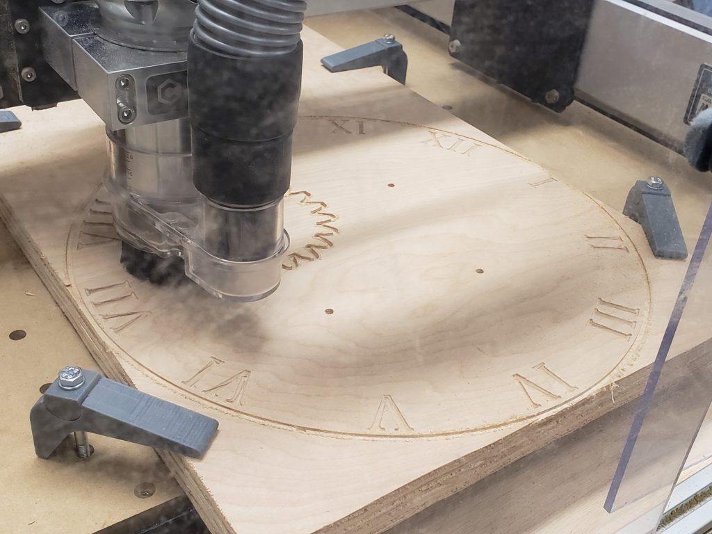
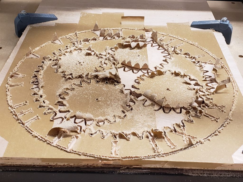
Now it’s time to cut everything out!
I ended up having to cut out two different sets of the gears. The first set wound up having the letters on the ring gear slightly offset. Somehow I managed to reset the zero on the X-axis between CNC operations. Otherwise, the gears meshed well enough. Perhaps just a little tight…
The frame which houses the clock was made by cutting out separate pieces of plywood and stacking them together. Each layer was glued and fixed with brad nails. I 3D printed a motor mount to fix the stepper motor to the back frame. I also 3D printed some standoffs which keep the planet gears co-planar with the ring and sun gears.
Electronics and Controls
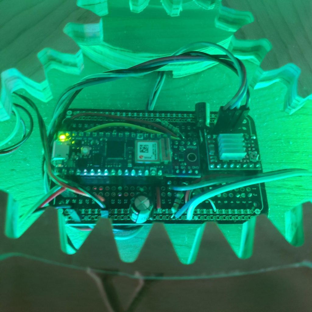
I choose to use an Arduino Nano 33 IOT for this project. The Nano form factor fit inside the clock nicely and the IOT version also came with WiFi and real time clock (RTC) chips that would prove useful later on. I would also need a stepper motor driver to control the NEMA 17 stepper I had selected. At a rated 1.2 Amps, the motor would be far too much for the Nano to drive on its own.
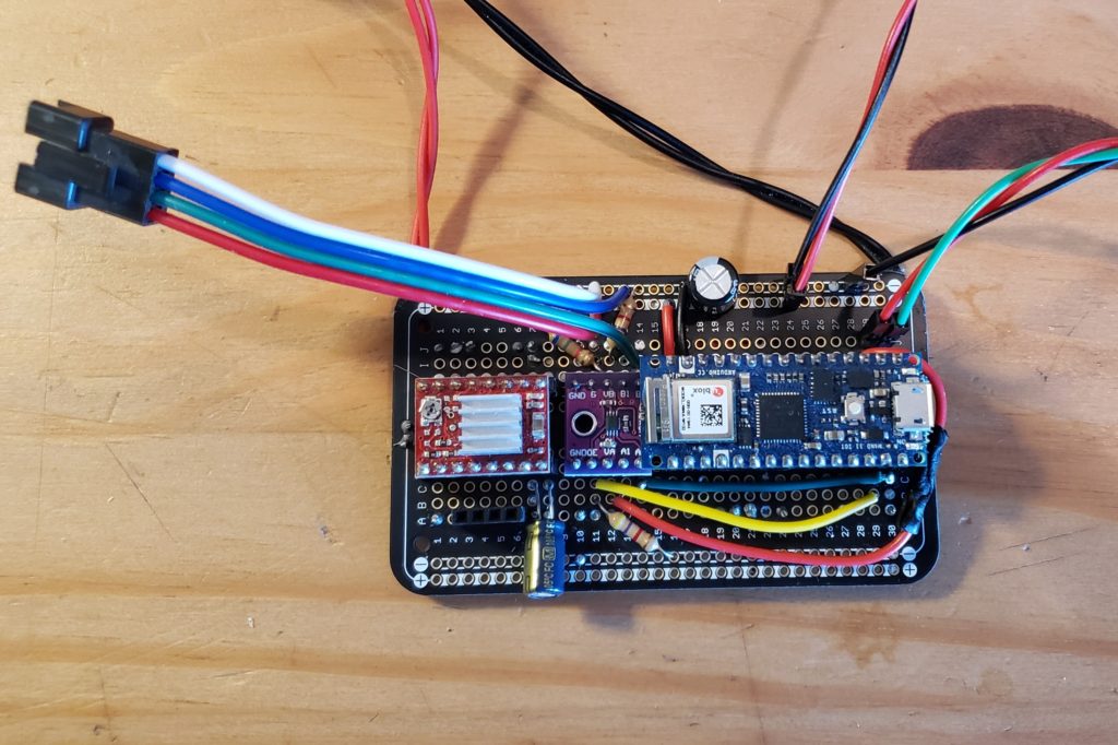
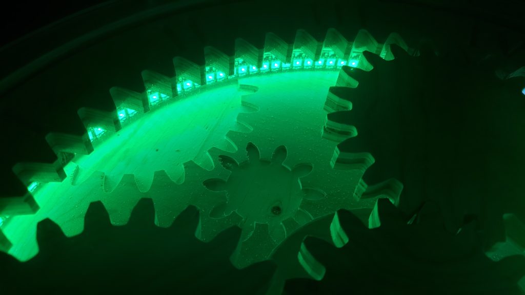
Late in the build, a friend gave me the idea to add an LED strip that could be used to keep track of the minutes. I thought this would be a great idea and started experimenting with a strip of high density LEDs (WS2815). I immediately ran into issues trying to convert the Nano’s 3.3V logic to 5V logic for the LED strip.
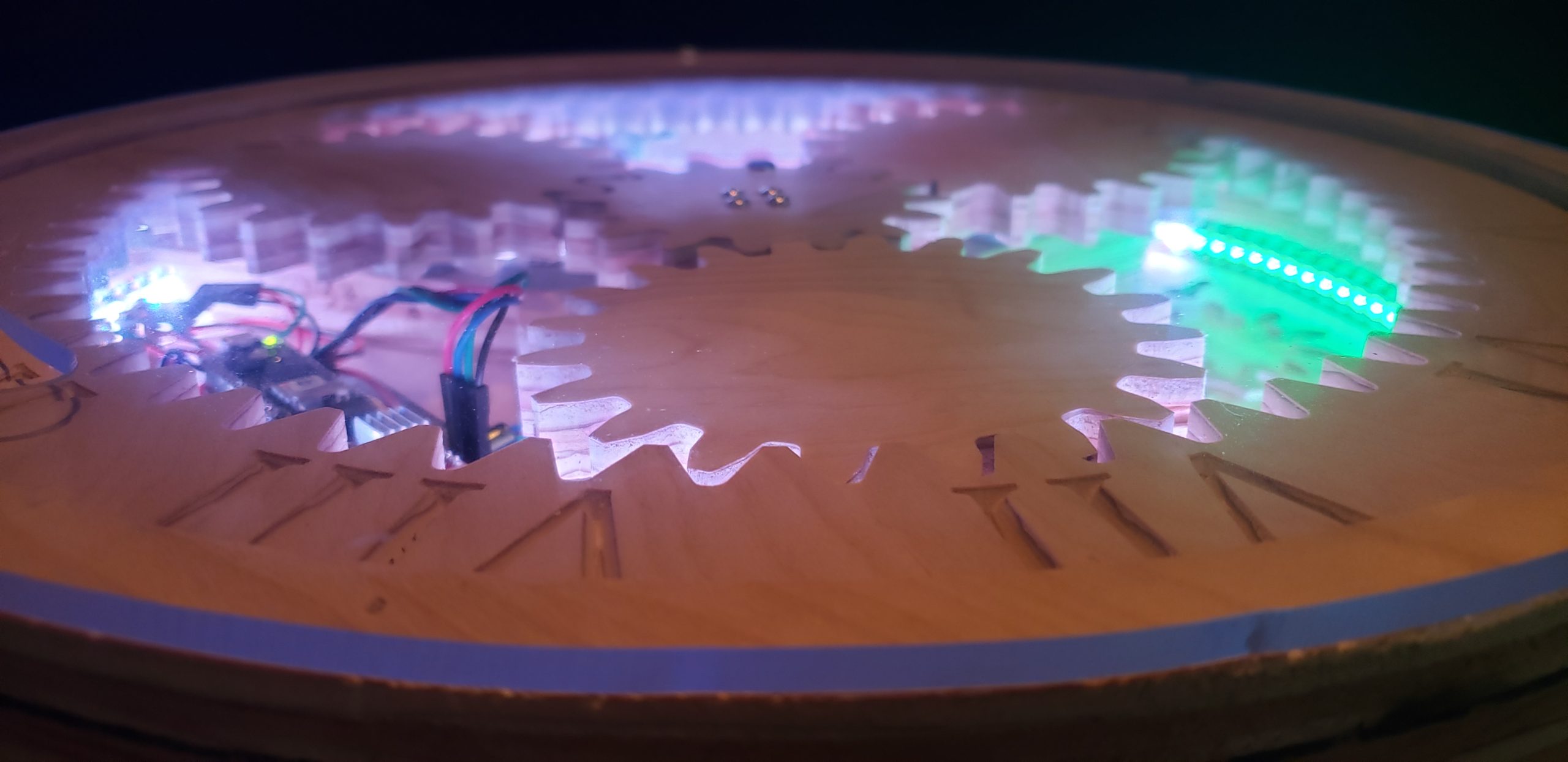
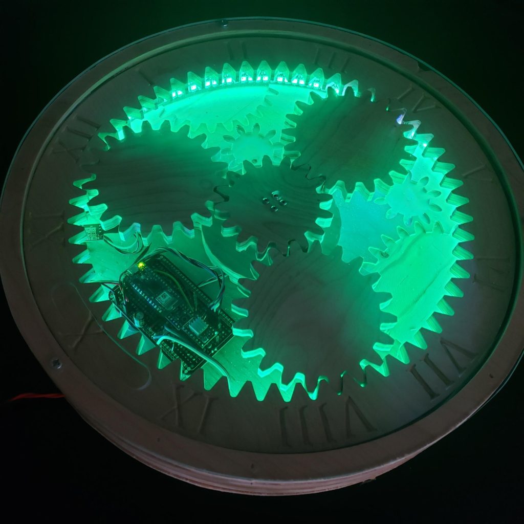
For starters, the solder-able breadboard I was using was already pretty full (notice in the picture how I had to forgo socketing the chip to keep it short enough not to touch the Nano). Second, the WS2815 LED strip requires a PWM input operating at 800 kHz. Most of the logic level shifters online use mosfets with charge times that would obfuscate the signal. The mosfets wouldn’t be able to charge up before the input signal goes low again.
I learned all of this the hard way by experimenting with a couple of cheapo-logic level shifters off Amazon. The LED strip would just flash random lights and general garbage. Eventually, I discovered the TXS0102 chip from Texas Instruments (with help from this site http://happyinmotion.com/?p=1247). Despite being designed for I2C communication (with a standard frequency of 400 kHz) the TXS0102 chip is capable of 800 kHz frequencies.
Since the stepper motor can’t keep track of its position after a power cycle, I would also need a way to “home” its position. I chose to do this with a Hall effect sensor. A Hall effect sensor triggers a digital signal whenever it detects a magnet. I made a small bracket on my 3D printer for the magnets and mounted them to the underside of the ring gear underneath the 1st hour. With this, the clock would always be able to orient its position relative to where the 1st hour is, even if it lost steps or was powered off.
Programming
If you would like to view the code in its entirety, the Arduino code for this project can be downloaded from GitHub.
After initialization of the different pins and libraries needed for the project, the clock “homes” itself with the following code.
bool homeRing() {

  //Rotate until HALL_PIN triggered or one revolution
  solidLED(CRGB::Yellow);
  digitalWrite(SLP_PIN, HIGH);
  stepper.moveTo(steps_clock_rev);
  while(digitalRead(HALL_PIN) == 1 and stepper.currentPosition() < steps_clock_rev)
    stepper.run();
  stepper.stop();
  solidLED(CRGB::Green);

  //Checks for fail state and then sets the new zero
  if(stepper.currentPosition() >= steps_clock_rev){
    digitalWrite(SLP_PIN, LOW);
    return false;
  }
  else
    stepper.setCurrentPosition(5140);
    stepper.moveTo(ratio_steps*((rtc.getHours()%12)*3600 + rtc.getMinutes()*60 + rtc.getSeconds()));
    stepper.runToPosition();
    digitalWrite(SLP_PIN, LOW);
    return true;
}
The clock sets the LED strip to yellow to indicate that the homing operation is in progress. The clock runs clockwise until the Hall effect sensor is triggered or a revolution is completed. If the Hall effect sensor is triggered the clock saves its current location and proceeds to the current hour. If the clock completes a revolution, then an error state is thrown.
The clock keeps track of the number of seconds that have passed using the real time clock (RTC) built into the Nano IOT. This time is set to current time once at startup by connecting to the WiFi network and pulling the current time from the router.
// 11,200 steps for full clock revolution
// 43,200 secs for full clock revolution
// 144 LEDs for a full clock revolution
float ratio_steps = (11200.0/43200.0);
float ratio_LED   = (144.0/3600.0);
void loop() {
  epoch_steps = (rtc.getHours()%12)*3600 + rtc.getMinutes()*60 + rtc.getSeconds();
  epoch_LED   =  rtc.getMinutes()*60 + rtc.getSeconds();

  //Stepper loop
  stepper.moveTo((int)(ratio_steps*epoch_steps));
  if(stepper.distanceToGo() > 233)                  //Update the stepper motor every 15 minutes
  {
    digitalWrite(SLP_PIN, HIGH);
    delay(150);
    stepper.runToPosition();
    digitalWrite(SLP_PIN, LOW);
  }

  //LED loop
  current_LED = ((int)(ratio_LED*epoch_LED) + NUM_LEDS/2)%NUM_LEDS;
  if(prev_LED != current_LED)
  {
    prev_LED = current_LED;
    for(int x = 0; x < NUM_LEDS; x++){leds[x] = CRGB::White;}
    if(current_LED >= NUM_LEDS/2)                                           //if the current LED is in the first 30 minutes of the clock
    {
      for(int x = current_LED; x > NUM_LEDS/2; x--){leds[x] = CRGB::Green;} //then fill the strip up to that LED
    }
    if(current_LED < NUM_LEDS/2)                                            //if the current LED is in the last 30 minutes of the clock
    {
      for(int x = current_LED; x > 0; x--){leds[x] = CRGB::Green;}          //then fill back to the 30 minutes mark
      for(int x = NUM_LEDS-1; x > NUM_LEDS/2; x--){leds[x] = CRGB::Green;}  //and fill forward from the 0 mark
    }
    delay(150);
    FastLED.show();
  }
}
Two ratios (ratio_steps and ratio_LED) were developed to drive the stepper motor and the LED strip. The first ratio is calculated by taking the number of motor steps in a complete rotation of the ring dividing that number by the number of seconds in 12 hours. The second ratio is calculated by taking the number of LEDs in the strip and dividing that number by the number of seconds in 1 hour. By multiplying those ratios by the current number of seconds in the day (as determined by the RTC), we arrive at the appropriate motor position and LED.
//Stepper loop
  stepper.moveTo((int)(ratio_steps*epoch_steps));
  if(stepper.distanceToGo() > 233)                  //Update the stepper motor every 15 minutes
  {
    digitalWrite(SLP_PIN, HIGH);
    delay(150);
    stepper.runToPosition();
    digitalWrite(SLP_PIN, LOW);
  }
The stepper loop only runs every 15 minutes. When the loop isn’t running, the stepper driver is put to sleep (SLP_PIN). This is for two reasons: First, I ran into an issue with missing steps when I advanced the motor one step at a time. Second, I ran into overheating issues when the motor was run continuously. This is a part of the project that I am still working on and I’ll expand on this more at the end.
  //LED loop
  current_LED = ((int)(ratio_LED*epoch_LED) + NUM_LEDS/2)%NUM_LEDS;
  if(prev_LED != current_LED)
  {
    prev_LED = current_LED;
    for(int x = 0; x < NUM_LEDS; x++){leds[x] = CRGB::White;}
    if(current_LED >= NUM_LEDS/2)                                           //if the current LED is in the first 30 minutes of the clock
    {
      for(int x = current_LED; x > NUM_LEDS/2; x--){leds[x] = CRGB::Green;} //then fill the strip up to that LED
    }
    if(current_LED < NUM_LEDS/2)                                            //if the current LED is in the last 30 minutes of the clock
    {
      for(int x = current_LED; x > 0; x--){leds[x] = CRGB::Green;}          //then fill back to the 30 minutes mark
      for(int x = NUM_LEDS-1; x > NUM_LEDS/2; x--){leds[x] = CRGB::Green;}  //and fill forward from the 0 mark
    }
    delay(150);
    FastLED.show();
  }
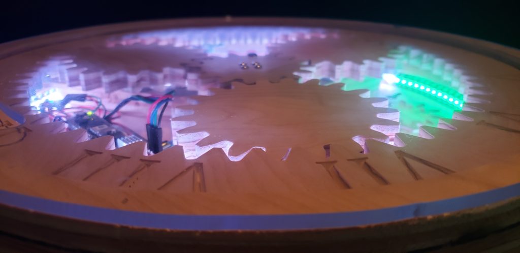
The LED strip is positioned such that the first LED is at the 31 minute mark and the last LED is at the 29 minute mark. This was done to shorten wire runs. As a result, the code needs to shift the output of the ratio over with some modulus math. After that, the strip is filled with green according to how far the minutes have advanced. The conditional cases in the LED loop account for whether the current LED is before or after the 0th LED with respect to the physical LED strip.
Conclusion
The following video shows the clock powering up and running through the code. The white LEDs at the beginning indicate initialization of the WiFi connection and importing all the libraries needed. When the LEDs turn yellow, the clock is running the home function. After the 1st hour (under which the magnets are mounted) reaches the Hall effect sensor (at around 7 o’ clock) the LEDs turn green to indicate that home has been found and the clock heads towards the current time. Finally, when the clock reaches the current time, green LEDs fill up to the current minute.
Here’s some more pictures…
It’s not done yet… I still need to do some finishing touches like painting the letters, applying a finish, and eliminating some bugs in the code (in particular when I roll over from 11:59 to 12:01). I also need to re-cut the top planet to be slightly smaller (it’s causing some jamming issues).
I’m pretty happy with the final product. If I had to do it again, I would use some nicer plywood like Russian Birch that would leave cleaner edges.

